Rapid Prototyping technology as used on the Bombe Rebuild Project
When faced with the problems of making many different and often complex castings for the Bombe Rebuild it was decided to investigate the possibility of using modern techniques rather than settle for the traditional handmade wooden patterns. The cost was also a major factor.
The base castings and many of the more simple items such as the vertical and horizontal shaft bearing and the belt pulleys were made from moulds made out of wood in the traditional manner. However, the more complex castings such as the main gearbox casing (drive bracket) and the clutch magnetic case used Rapid Prototyping methods.
We used the following methods to produce the necessary patterns or moulds.
Laminated Object Manufacture (LOM)
Selective Laser Sintering (SLS)
EOS Sand Sintering
Our input to the Rapid Prototyping Centre was is all cases a.STL file. This was supplied ‘finished size’. To allow for casting shrinkage we had only to specify the percentage increase in the size required for the pattern and this the Rapid Prototyping Centre fed into their program without our team having to put in any more effort.
[The extract below has been taken, with the kind permission of Chris Ryall to only cover those techniques of Rapid Prototyping used in the Bombe Rebuild. For copies of the full paper please contact either of the authors at the University of Warwick]


Rapid Prototyping For
Rapid Castings
Chris Ryall & David Wimpenny
The Rapid Prototyping & Tooling Centre
Warwick Manufacturing Group
University of Warwick
1.0 Introduction
Rapid prototyping is a means of manufacturing 3-dimensional objects directly from CAD data. The main advantage of using this technology is the speed at which these modelling systems can generate complicated three-dimensional shapes.
One obvious application has been the use of rapid prototypes as patterns for casting. Models have been successfully used as sand patterns.
More recently the introduction of the EOS GmbH “sand sintering” rapid prototyping machine has seen the direct production of sand moulds. What influence this has on the casting industry remains to be seen, but its impact should be far-reaching.
This paper will discuss several of the major rapid prototyping techniques.
1.1 Rapid Prototyping
Rapid prototyping is a relatively new term for the generation of three-dimensional models without the need for machining or tooling. The production of models by machining relies on the removal of material until the required form is achieved. Rapid prototyping differs by adding material layer by layer until the desired shape is achieved. One advantage is that excess material is not wasted. The second advantage and the most important is the time taken to produce a model may be significantly reduced, generally, the more complex the model the greater the time-saving. Rapid prototyping, therefore, goes some of the way to rectifying the problems encountered with traditionally generated prototypes and patterns in terms of accuracy and time. This is only true of models with more complex geometry.
2.0 The basic process and main systems
Rapid prototyping machines process CAD data by slicing the model, each layer being typically 0.1-0.25mm. The machine then uses this sliced data to construct the model layer by layer. Each layer is in turn bonded to the previous, the models therefore having a stepped appearance on curved surfaces. The resolution of these steps depends on the thickness of the laminations. Post processing is usually required to improve the surface finish. The main commercial RP systems will be briefly mentioned, as there are numerous others.
2.1 Stereolithography (SLA)
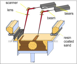
Figure 1: Schematic Diagram of the Stereolithography Process
The basic process is shown in figure 1. The STL (standard triangulation language) file of the proposed component is sliced by software. Each slice is then hatched on to the surface of a photosensitive ultraviolet curable resin with a “swinging” laser. Where the focused beam of the laser strikes the surface the resin is cured. Each slice is typically 0.13mm thick (0.0052″). After each layer is cured the partially built model is lowered in to a vat of resin by one layer thickness. A recoating blade then lays a thin film of uncured resin over the surface of the resin.
Overhanging portions of the model are supported by a lattice that is automatically generated and incorporated into each layer by the software. The model is built on a support lattice to prevent direct adhesion to the recoating table, thus allowing the model to be removed relatively easily on completion of the build. On completion of the build the model is carefully removed from the platform and washed in a solvent to remove the uncured resin from the surface. The model is then placed in a ultraviolet oven to harden any uncured resin.
2.2 Laminated Object Manufacture (LOM)
LOM was developed by Michael Feygin of Helysis. This process laminates thin sheets of film, the laser in this instance has only to cut the periphery of each layer, unlike SLA that has to scan the whole area of any one slice.
The build material is fed off a supply roll on one end of the machine. This material, usually paper, is precoated on one side with a heat curable resin, which is used to bond one slice to another. A heated roller then passes over the work area bonding the new slice to the part built model. A finely focused laser then cuts the periphery of the work area. The laser is focused to cut one laminate. Excess paper around the model acts as a support for the model during build. To aid removal of the model the excess paper is hatched by the laser. The block of paper containing the model is then lowered to allow a new layer to be fed across the work area. The model is then raised and the heated roller bonds the next layer to the previous one. To decrease the build time it is possible to build the model in double or triple laminates. This requires the laser power to be increased. This has a disadvantage in that the stepped effect is more clearly defined. Post processing of the models consists of the removal of the excess paper from around the model.

Figure 2: Schematic Diagram of the LOM Process
2.3 Selective laser sintering
The SLS process uses powdered materials. This is one of the systems major advantages, because, in principle, a model could be built in any fusible powdered material. Currently the range of materials includes nylon, glass filled nylon, polycarbonate, wax and metals.
The laser scans each slice fusing the powder, to the previous layer. As with all of the techniques mentioned so far the model is built on a table which lowers after completion of each slice. A fresh layer of powder of the required thickness is then rolled across the top of the cylinder and the process is repeated. Excess powder remains in place around the model to act as a support during the build. On completion of the build the excess powder is brushed from the surface of the model.
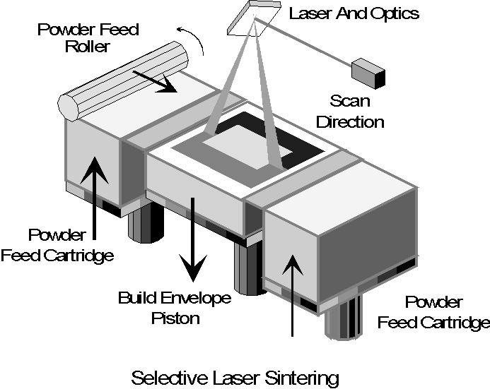
Figure 3. Schematic of the SLS Process
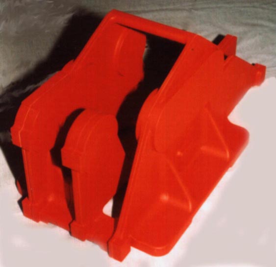
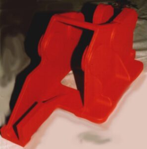
Here are views of our main Bombe Gearbox (Drive Bracket) pattern. It is made in eight parts using the techniques described in this article. All that has been done since delivery from the Rapid prototyping unit is the addition of some final filleting, not possible with our level of CAD, light rubbing down and a coat of pattern varnish applied.
2.3.1 EOS Sand Sintering
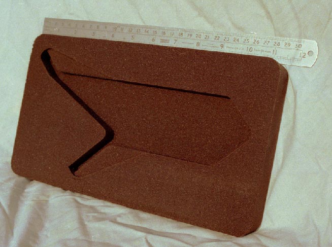
Photograph 1. This Bombe Jack Frame Stop Sand Moulding was Core Produced on Eosint S 700 Direct Croning System
One of the biggest steps forward for casting has occurred with this technology. A German company, EOS, has recently released another variation of this process called Direct Croning® named after the widely-used Croning shell process which uses a phenolic coated foundry sand as the fusible material. It is now possible to build sand moulds with integral cores directly. Removing the need for sand patterns and core boxes. The machine is capable of producing forms that are typically very difficult or near impossible using conventional techniques. A typically complicated core produced in six hours by the Eosint system is shown in Photograph 1. In principle it should be possible, provided the CAD, data were accurate and free from design errors, to produce a mould for a cylinder head in a matter of days. Generally, any alloy that can be used for sand casting can be used with this route. The surface finish of a casting from a sand-sintered mould is reported to be similar to that produced from a typical green sand mould. The working envelop of the S 700 sintering machine is 720 x 380 x 380 mm and utilises two lasers for the production of moulds. Since its release, German automobile manufacturers BMW and Mercedes Benz have each bought two machines for the production of prototyping castings.