FINAL DRUM ASSEMBLY AND TESTING
When the solid and wire links are all fitted the cover shown bottom right below plus the clip assembly, the escutcheon and other items are assembled. A centralising mandrel (not shown) is used to align all the parts before final tightening up.
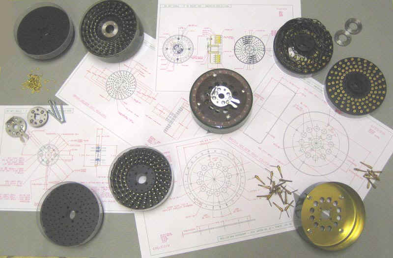
The photograph below shows all the parts required to make just one drum together with the engineering drawings that we produced at the beginning of the project.
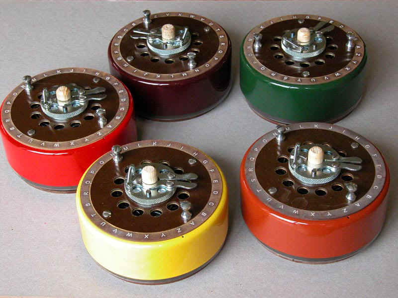
Below we have an example of each completed drum. Before the covers were fitted they were painted in the same five colours as they were in WWII. The five colours relate directly to the roman numerals used by the Germans to identify their Enigma machine wheels.
Three more colours were added for thr German Surface Fleet wheels
As can be seen they are mounted on temporary supports that help to protect the brushes. This is something that was not in use in WWII.
Below is a specialist piece of test gear that was made by Chris Carter to a design by Ron Rous, for testing the 26-way cabling and wired items on the Bombe. Mike Hillyard made a selection of adaptors so that this can be used to check drum wiring, Letchworth Enigma wiring and Reflector Plugboards for correct connections and shorts. In this particular test a drum is being tested. If correctly connected the ‘Go’ path and the ‘Return’ path will cancel each other out. In this test, a voltage is applied by the 26-way rotary switch and if all is correct the LED at its ‘tip’ will be lit. It is a very quick test to rotate through all 26 positions to ensure that the ‘light follows’.
In other applications, the LED will indicate the letter transposition for a given input.
