The American Naval Bombe N-530
Printing
This subsystem includes the associated stepper motors on the relay chassis and the 20 power valves on the printer control chassis.
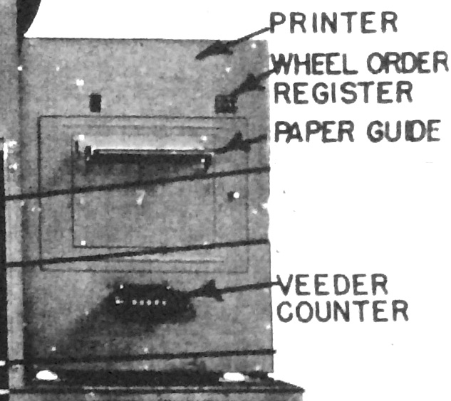
PRINTER FRONT VIEW
The printer motor is powered from the standard American supply of 220 v ac, three-phase. This runs continuously and is geared down to produce the main shaft speed at 57 rpm.
Through a single revolution clutch, a solenoid activates this clutch and allows the type wheels to perform a single revolution.
However, if a latch is set by the input from the high current 6Y6 pentodes, on the Printer Control Chassis, this will hold it in this position until the actual print time
There are 24 6Y6G pentodes that can carry the high current needed for the 24 Latch Solenoids. We don’t have the full details of internal circuits of the printer but it is very likely that there is a master commutator attached to the main printer drum shaft that feeds the input to 24 AND gates. When a letter from this main commutator coincides with a letter on an input cable the latch solenoid is activated and this allows a toggle to ‘catch’ the letter of the matching letter wheel. This is ‘caught’ until a full rotation is complete and the ‘sprocket wheels’ will then be in the correct position.. An alignment bar then accurately positions the type wheels. The type wheels are then forced against the printer ribbon and the data will appear on the printer paper in their proper column spacing.
The left hand three columns are used for the machine number
Every time the drum makes one complete revolution the paper is moved on one position.
The machine number consisting of 3 numbers is set by hand
This is a rear view of the Diagonal Board to Printer Cables
For every column of the printer, there could be a 26-way cable feeding it. The position indicator four cables are normally left plugged in. Other cables are plugged to sockets on the Diagonal Board Chassis.
Each Printer Column which is used is plugged into the printer sockets of the Diagonal Board. The image above shows most of the cables from the back of the printer plugged into the lower row of sockets on the Diagonal Board
There are 26 sockets on the Diagonal board that printer cables can be plugged into. Up to 20 cables can be plugged here. The actual location is defined in the menu set up sheet
Multiple Lines of print
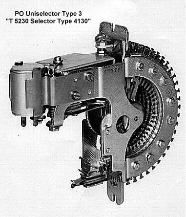
Stepper motors or Uniselectors as the British call them
There are two of these on the relay chassis but as they both carry out very similar functions, only one will be described this time
Above is a 25-way British uni-selector
These are very similar to the American version and may well be that those in our British telephone exchanges were a copy of the American version.
25 and 50 way were the most common but the N-530 needed 26 ways. The standard 25 way was used but with additional relays, a 26th state could be achieved.
The stepper motor provides power to the diagonal board and moves one step with each line of print.
A typical print out would have 26 lines. The difference between each line of print is that power is connected to the diagonal array at different junctions.


