The American Naval Bombe N-530
Indicator Commutators
Unlike our BTM machine where one has to look at the position wheels and then write this down, on the N-530 this printed
The commutators used for this are mounted on the rear of the machine. The commutators are identified as A, B, C and D. Confusingly they are at levels D, C, B and A respectively
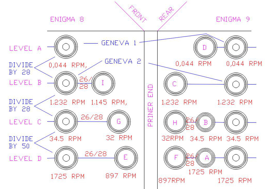
The diagram above shows the location of each commutator and the speed at which they rotate
When the machine comes to a final halt the four commutators will be at a position where the arms on the commutators are where this information can be recorded. All four are basically a 26 position rotary switch. There are also continuous segments to provide the input power and another ring with 26 segments. This description applies to all four commutators but in the case of C and D, there is also a final stop segment. The D commutator is only used in a 4wheel run
The 26 segment connections of each commutator are connected to a Jones socket. These are shown on the image on the final page of this instalment with Jones plugs inserted. A, B, C are visible with ‘D’ assumed to be below ‘C’. These four cables are connected to the connections leading to the printer (three if a 3Wheel job).
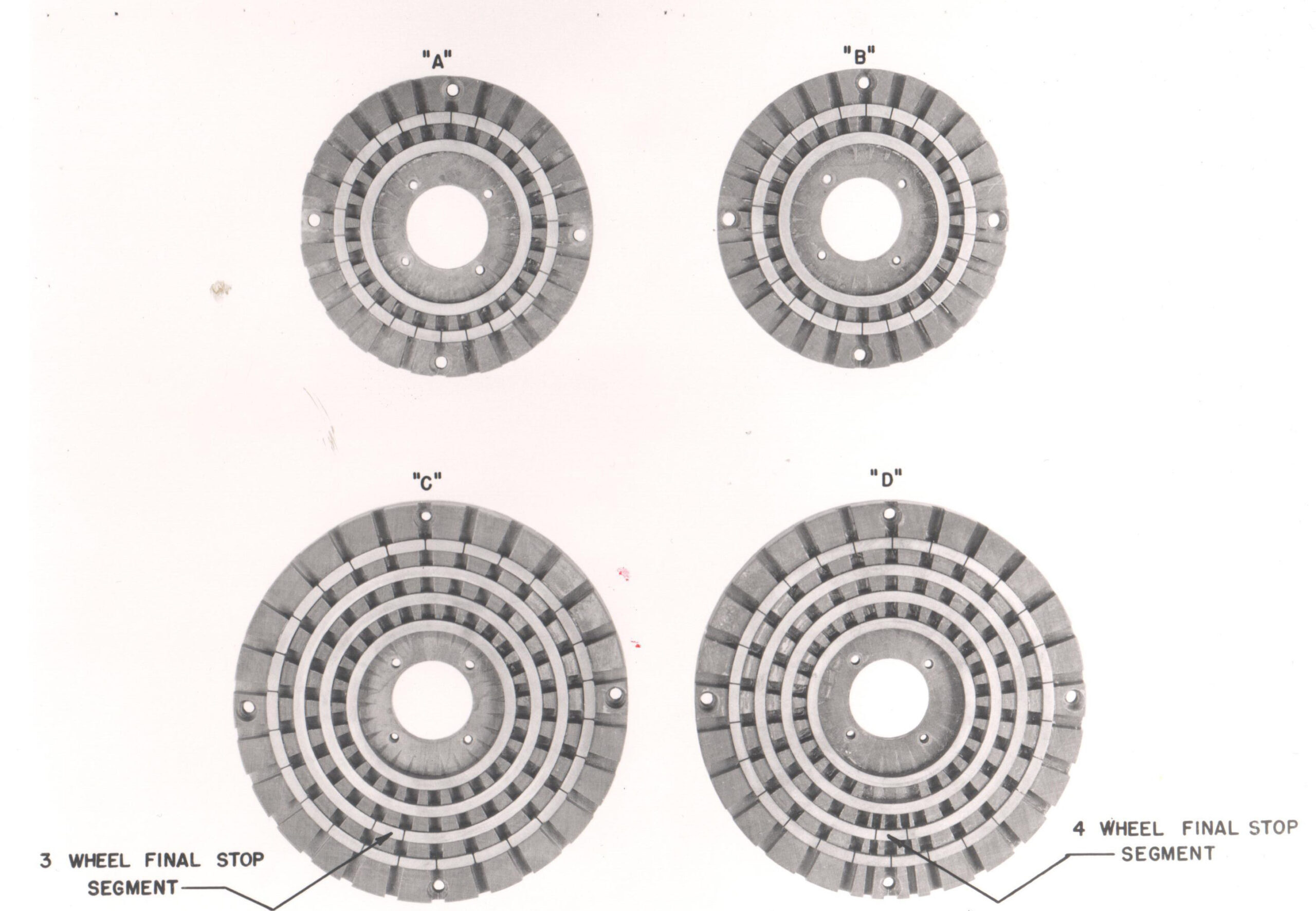
Above is a view of the segment details of each commutator
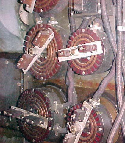
This is a close up of commutators H, B, F and A
H and F are Location Commutators that define the final stop position. This will be described in a future chapter