The American Naval Bombe N-530
Mechanical Aspects
Now with a menu loaded, the Diagonal Board connected and an input letter set on the Neon Chassis (more about this in a future Chapter) we can consider getting the machine going.
The main drive motor is a three-phase 200V that drives forward motion but when not powered can rotate in the opposite direction.
To the far left is the drive belt to the zero rotation unit
To the far right is the drive to the gearbox
This motor drives various units but mainly the sealed gearbox. The main output of this is the drive to all Letchworth Enigmas
The layout of the machine is that the levels are: fastest at the lowest level ‘D’ running at 1725 rpm and then reduced to 34.5 rpm at level ‘C’. Then it is further reduced to 1.232 rpm at level ‘B’. Level ‘A’ is reduced to 0.044 rpm but this level is only engaged on a 4wheel job. There is a clutch in the gearbox that disconnects this level
Although the specification defines rotational speed in rpm these are not linear because levels A and B have Geneva Gears in their drive which rotates the wheels so that brushes are on segments as long as possible and then rotate rapidly to the next segment. (see: Geneva explanation at the end of this chapter)
The output of the gearbox at all four levels is by horizontal shafts, running the full width of the machine. At each wheel shaft, there is a gear that engages with the horizontal shaft. There are also other drives out of the gearbox that drives timing wheels.
We know on BTM machines that when a stop is detected or HIT as the Americans describe it, the medium and slow drum drives are disconnected but the fast drum position is recorded on the stop and cancel relays. When the machine is running slow enough the clutch is engaged when the machine is back to the original stop position.
On the N-530 the process is different but still has to be returned to the original state when the STOP/HIT took place and where information relating to the HIT can be recorded.
The N-530 achieves this by recording the E and G position on one of the two 26 thyratron groups. An electrically activated brake is then applied until the machine stops. This stop is detected by what is called the zero rotation unit. This is a small dynamo that generates power when rotating but has incorporated in it a zero voltage detector that makes a contact when there is no more voltage being generated
When this happens, another small motor geared to the main shaft runs the machine back slowly until the machine is in a position where the thyratron set earlier, match the position of the machine. At this point, a mechanism locks the machine from further rotation. This is now where the position wheels and other information taken from the Diagonal Board can be printed. More on this in chapter 10.
If the HIT was detected but did not satisfy further testing the machine restarts without any operator action, looking for another HIT.
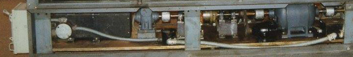
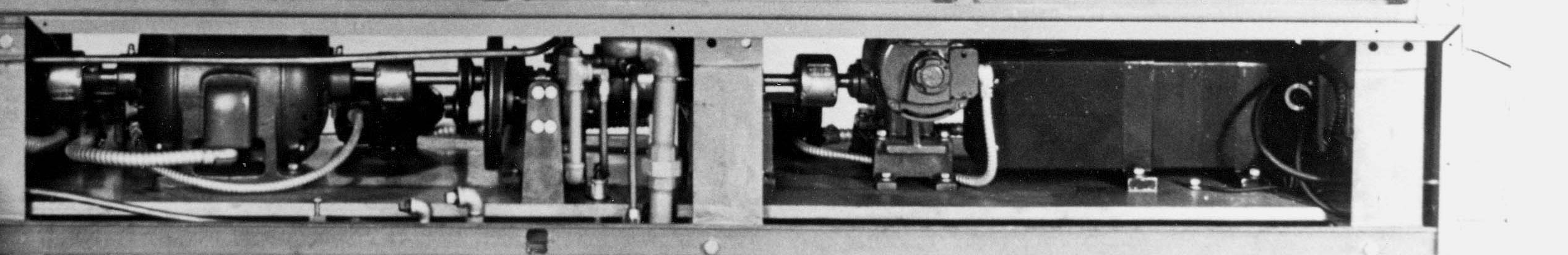
FRONT VIEW
The components above are left to right
- AC Mains Switch
- Sola Regulator
- Rewind motor gearbox
- Chain Coupling
- Magnetic rewind switch
- Belt drive to zero rotation unit
- Forward drive motor
- Drive to gearbox
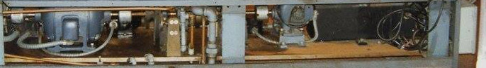
REAR VIEW
The components above are left to right
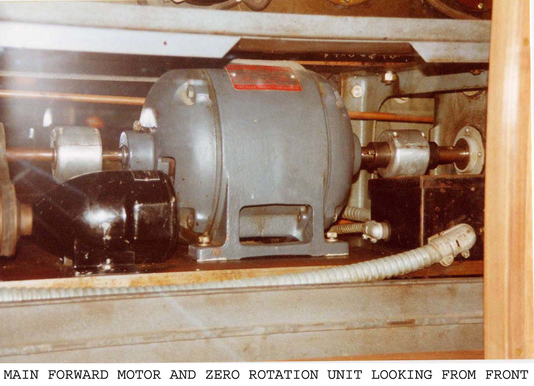
- Main forward motor
- Belt drive to zero rotation unit
- Oil pump
- Rewind Motor
- Sola regulator
- DC switch
I have shown two very similar views because some areas are more easily seen than the others
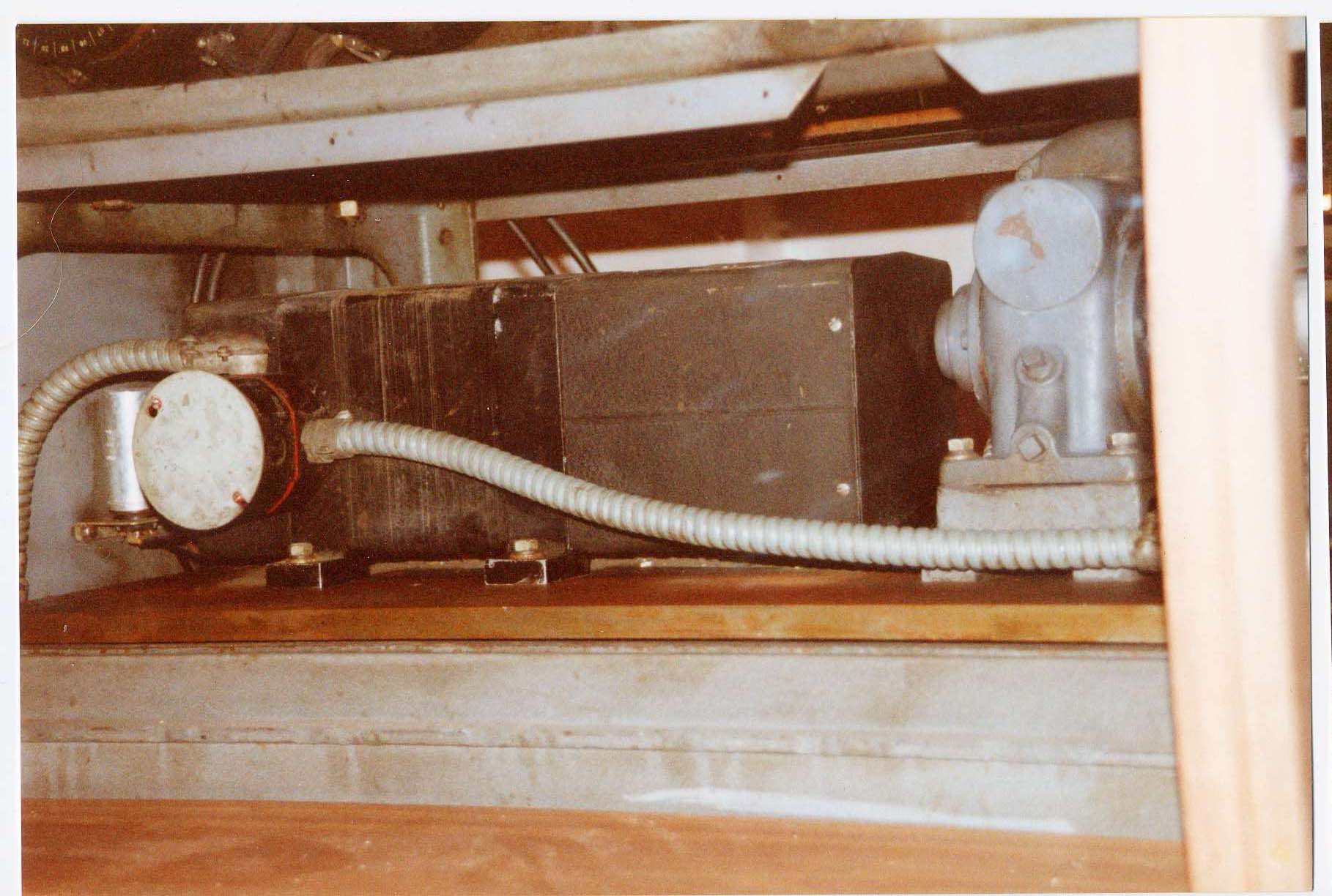
Close up of SOLA Regulator and rewind motor drive
The SOLA Regulator is described in Chapter 06
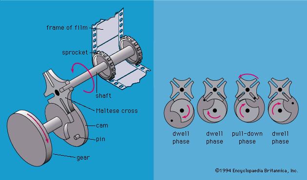
GENEVA MECHANISMS
Many readers will already know about Geneva drives but there might be some who have not previously heard about it.
The most common use was in film projectors where a frame would be held for a while and then quickly moved on to the next frame