OTHER PARTS STILL REQUIRED
MAY WE RESPECTFULLY POINT OUT THAT WE ONLY REQUIRE THE PARTS BELOW THAT FULLY MEET OUR SPECIFICATION. WELL INTENTIONED PEOPLE HAVE SENT US OTHER PARTS WHICH WE CANNOT USE IF WE ARE TO ACHIEVE OUR AUTHENTICITY STANDARDS. THESE OUT OF SPEC. PARTS WE WILL PASS ON TO OTHER NEEDY CAUSES WHERE POSSIBLE BUT WE WOULD HATE TO SEE PARTS WASTED.
LUBRICATION PUMP
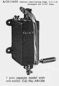
The British Bombes had a lubrication system based on a Tecalemit ‘one-shot’ system. Versions of this were supplied for car and lorry chassis lubrication systems and also for complex machinery that had many points requiring lubrication. In the case of our version of the Bombe, oil is fed to 177 places through 5/32″ OD brass pipe and large numbers of junctions to precision metering valves. We have found a pump which will serve our purpose for the time being. This was recovered second hand having previously been fitted to a 1950s Rolls Royce Car. However, this is not quite the correct type. Hence we are asking supporters to look out for the correct one which we can easily fit if available. The type we require is shown below. It could be marked PC1B or AB 1206. It is possible that it would have a later type Tecalemit Logo and possibly be marked up as a Bijur, Girling or Luvax product. All these companies dealt in these pumps at one time or another. To give an idea of size the main body is 6 inches tall.
More details of the lubrication system
DC MOTOR AND SOURCE OF DC POWER
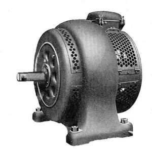
We have a DC motor of the correct age and voltage but this is manufactured by Crompton Parkinson. We actually need a 3/4 or 1 H.P. 220 volt DC motor Shunt Wound, two speed 800/1600 r.p.m. made by Thompson Houston.
The image above shows a motor very similar to the type we require. The main central body is around 12″ in diameter
CONDENSERS
These days they would use the name capacitors but we like to stick to W.W.II terminology where possible. Condensers used in our Bombe are fitted solely for the purpose of suppressing sparking across contact or relay points.
There are two types fitted to our Bombe
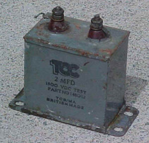
Condenser Paper 2.0 mfd. 1500 VDC 1 off
Condenser Paper 0.5 mfd. 1500 VDC 12 off
There are slight variations on the official specification where the working voltages have been reduced to 750 VDC and the physical sizes reduced slightly. However, our samples taken from the 1940s punched card equipment measure.
Height (2 1/8″ over body) – (2 3/4″ overall)
Width of body (2 1/8″) – (3″ over fixing lugs)
Depth – [2 mfd., 1 3/8″] – [0.5 mfd. 3/4″]
We have most of these condensers and surprising they all turned out to be sound. However, in six cases we have slightly incorrect types fitted. These are electrically correct but have slightly different body shapes and fixing brackets. We would also wish to have spares available. If anybody can help we would be grateful.
RELAYS
BTM – BTM Multi Relay
If you can help please contact our Project.
EARLIER IN THE PROJECT WE WERE LUCKY IN FINDING THE RESISTORS AND SIEMENS RELAYS THAT WE REQUIRED. WE HAD CONSIDERABLE HELP FROM EX GPO EMPLOYEES WHO TRACKED DOWN THE PARTS THAT WE WERE SHORT OF. WE ARE VERY GRATEFUL FOR ALL THEIR HELP.
THE ITEMS BELOW ARE JUST INCORPORATED FOR INTEREST SAKE.
RESISTORS
STANDARD BTM
BTM used mostly ‘clip in’ resistors either straight and simple or versions where the body extended outwards to give more cooling area. Ex BTM engineers and other found enough of suitable values for the larger versions. However not a sufficient number were found; over 100 so we had more made. A firm in Germany produced and donated these to the original specification
SPECIAL NON-INDUCTIVE
We recovered formers and rewound them to the correct values
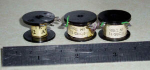
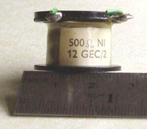
An ex STC member of our team said that these looked like telecomms resistors. A quick investigation revealed that what we were in fact looking for were Resistor Coil Number 12 600 ohm non-inductive.
Because we realised that trying to get hold of so many at the same value might be expecting we rewound them using insulated resistance wire.
The images below show the type but not the actual values we required. The diameter is approximately 15/16″ and the height a little over 5/8″.
RELAYS
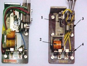
SIEMENS RELAY OF THE TYPE PREVIOUSLY REQUIRED – ON RIGHT
Our machine uses 104 double ‘Siemens’ type high-speed sense relays. These are similar to two of the more readily available single versions but mounted onto a new double base. They are mounted in the Bombe on the left-hand side of the open jack frame gate. We have detailed manufacturing drawings of these relays and one original sample. It was very unlikely that any more originals could be found so we decided to make the rest ourselves. They were not used to the best of our knowledge in any significant numbers on BTM Punched Card equipment until after WWII.
As a slight digression, I would like to point out that there were different sense circuits implemented throughout the life of the Bombe. The two most commonly used either the standard BTM ‘A’ type differential relay in “balanced” mode or the faster Siemens type used in a Whetstone bridge arrangement.
Returning to Siemens Relays, we know that other organisations such as the GPO and the railways used these in the 1940s and in following years. We acquired around 300 single relays (see photographs above) but in most cases, the coil resistance was too high. We had to rewind these. About 100 of them are of the latter type shown on the left. These can be identified by
- A more complex Armature Spring
- A coil with a simple symmetrical bobbin and no integral retaining feature.
- An adjusting screw without a tommy bar hole
- A contact assembly without a tommy bar hole or retaining clip
Type H95B was our favourite choice as this provided all the early parts required plus two 145 ohm coils. The exact specification is 160 ohms but 145 ohms comes within the tolerances permissible.
Please note that we only use one coil in our application. Two are shown in the left-hand photograph.
