NEW DRAWING, RAPID PROTOTYPING & DATABASES
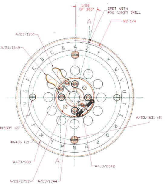
SMALL EXAMPLE OF ONE OF OUR NEW DRAWINGS
We used AutoCad software kindly provided by AutoDesk®. Our appeal for assistance, which appeared in the Spring 1998 issue of the Computer Conservation Society magazine – Resurrection Number 19, was very successful in recruiting additional AutoCAD draftsmen. In fact at our peak, we had a team of four redrawing the original drawings that were required for our rebuild. The drawings for the central mechanical core of the Bombe were mostly completed by the end of 2000. Not only were they complete as individual drawings but also in terms of full assembly drawings. What we then achieved was to construct major parts of the machine ‘on paper’ checking every part for fit as it is assembled with the others. This confirmed that the correct part was being used and that it was accurate. A few 1990s errors have been corrected but interestingly mistakes made back in the early 1940s have also been discovered. Fortunately these were easily understood and rectified. The result was that we have a more accurate set of drawings than was originally available. However, we do have far better tools available to us these days so this is to be expected.
We had our own large Plotters, which produced drawings up to 33″ [841mm] x 60″ [1500mm] and A0 size. This covered over 99% of our needs. A sponsor kindly provided the paper and plotter pens.
Altogether, we completed around 900 new drawings. Drawings for the electrical parts such as looms etc. were also completed.
Something of the order of 100 new assembly drawings have been produced.
Two major benefits of using Computer Aided Design emerged – The first was partly anticipated in that we can go directly from AutoCad drawings to the Computer Aided Manufacturing. We have had plates cut to shape on a Laser cutter and other plates punched to shape using a large computer controlled punching machine at Nortel Networks Harlow. Quite intricate parts are possible.
From 3D files that our team produced, we had a complex eight part casting pattern made at the Warwick University/Rover Rapid Prototyping & Tooling Centre. The casting incidentally was required to house the main Bombe gearbox. Gearbox & Clutch
A benefit we hadn’t expected and already mentioned above, was in creating assemblies ‘on paper’. Taking the individual component drawings and bringing these together not only created an overall assembly drawing for relatively little extra effort but it also picked up all the errors and omissions. Computer Aided Design is very unforgiving and demands that everything is correct. We picked up many minor errors during this process with a significant proportion of these being on the original drawings. This has led in turn into some detailed investigations, which took effort but was obviously by far the best time to carry this out rather than after metal had been cut.
It should be noted that the only drawings provided by GCHQ were those specific to the Bombe. Where standard 1940s Hollerith/BTM components are used we did not have any drawings and relied on donations of assemblies from contemporary punched-card equipment.
RAPID PROTOTYPING
One of our major technical requirements was to produce precision cast iron castings. For the smaller ones, we are using traditional wooden patterns where the cost was reasonable. We did however have one very large gearbox (drive bracket) casting which presented us with difficulty. A professionally made pattern would have be very expensive and we were advised to use modern CAD methods. Having a member on our team who had mastered the art of producing three dimensional drawing files we were well placed to proceed with this option. We were recommended to talk to Warwick University and subsequently visited the Rapid Prototyping Centre run then jointly by the Rover Group and the University and received encouraging support. The result was that we then had an eight part pattern made from modern material which was shaped using sophisticated computer controlled laser bonding and cutting equipment. Rapid Prototyping
The skills that we have acquired from this exercise in terms of 3D modelling was applied to injection moulding. Jack Plug mouldings were required in significant numbers and we kept the cost down by first producing the necessary 3D files.
DATABASES
We have a main Drawing and Component Database. A member of one of our teams, Dick Cromwell, laboriously entered over 3500 component descriptions. The need to keep tight document control of the photo-copying and redrawing exercises was been achieved by adding extra fields to this main database. This has since grown to include over 5000 records.
The more detailed database for our Target machine was completed and stands at 2250 records. Extra fields were added which included identification of similar materials etc. In this way, the database became our source of estimating, progressing, stock control and procurement.
Our original Target machine parts schedule was taken from a 1943 listing and whilst being of great help turned out when analysed in depth to be somewhat deficient. In fact, we have added about 7% to it because of our studies and ‘paper’ construction exercises. 7% may not seem a lot but actually represents 150 different additional drawings that would not otherwise have been produced. In many cases, each part type is needed in large volumes and what has been added represents nearly 8500 individual components.
Further machine specific databases need to be reproduced in the fullness of time. There are many other versions of the British Bombe that need investigating in detail even if we don’t actually build anything else. This is in addition to those already created by Roy Newbury, but these will be extracted from the main database rather than input afresh.
MAGNITUDE AND COMPLEXITY OF PROJECT
Letchworth built just over 200 Bombes in about 5 years. We only built one. However they had hundreds of people involved; around 30 people in the drawing office alone. BTM allocated vast mechanical manufacturing facilities to the bombe covering acres of manufacturing space. They had night shifts running and worked very long hours.
The sheer number of some of the parts we have had to make is mind boggling. For example, there are over 12,000 studs needed in the commutators and over 18,000 drum brushes. Something of the order of 50,000 cable terminations on nearly twelve miles of red wire were made. Around 17,000 screws of varying sizes hold the machine together.
To put it another way about 13 cwt [650Kg] of parts were assembled in the frame with most of these items weighing only a few ounces [grammes].