
DRUM COMPONENTS
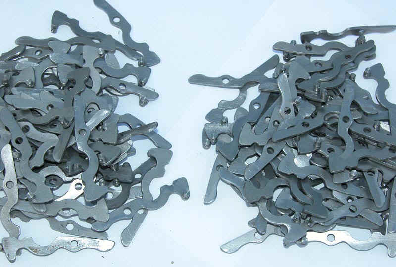
Each drum needs two clips. A selection of these are shown below
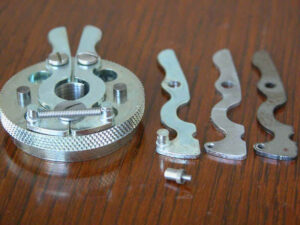
These are mounted on hubs as can be seen below. The hubs are quite complex as can be seen. From rough blanks the main dimensions were turned and then the knurling was added. Next the holes and counter-bores were machined by hand using jigs made by the team. The three holes were tapped before the separately made stops were pressed in place. The clip fixing screws were specially made before fitting. The clips needed spring posts made and riveted in place.
The brush assemblies (below) had all to be assembled by hand The posts were manufactured commercially by a CNC company but the rest was assembled by hand.
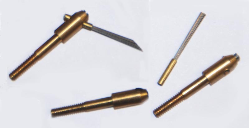
The brushes themselves were made up of 19 strands of 0.008″ diameter piano wire these were crimped used hand tools into a brass ferrule. The ferrule being cut by hand from standard brass tubing. When these were assembled they were fitted into the posts but first a very small 2-56 size slotted grub screw had to be started. These were not easy to obtain but eventually we found a supplier in the States; slotted heads are now rarely available. The assembly top left shows a brush assembly after having been ground to 30 degrees as described later. 104 of these assemblies were then fitted through the mouldings described elsewhere and held in place with brass 3-48 nuts.
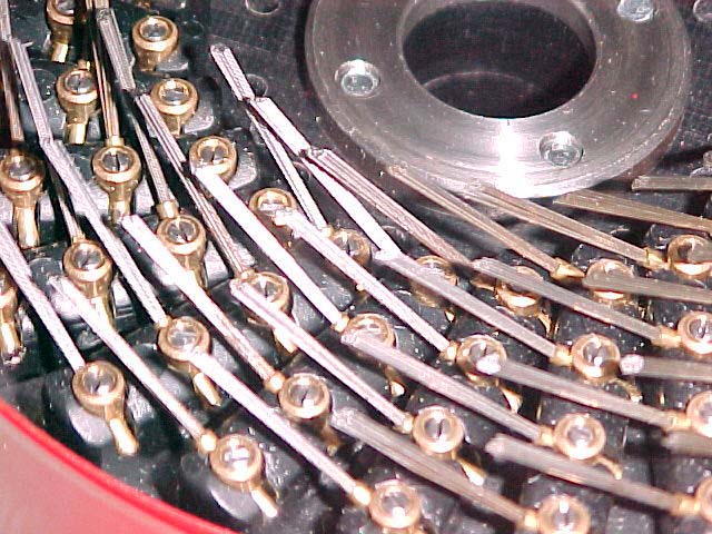
Below the brush assemblies have been fitted and in this photo they have already been ground to shape.
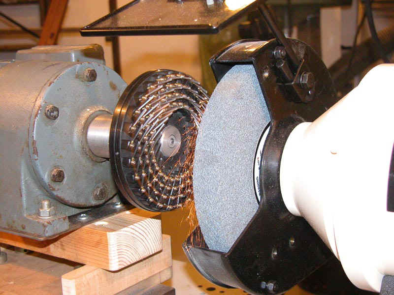
Below is the grinding set up used to bring the brush tips to shape at 30 degrees and to ensure that they are all the same height above the drum clips.
Not visible is the calibrated handwheel which is used to move the motor on which the brush holder plate assembly is mounted towards the grinding wheel face. The “stop” position is regularly recalibrated using a gauge (a dummy assembly) to compensate for wear on the grinding wheel. Grinding is done in two passes each lasting around 10 minutes. On the first pass the brush holder plate is advanced to within 20 thou of the final stop and is left grinding until very little sparking is evident, the brush wires themselves applying the load. This is then repeated with the final stop setting. Following grinding, a ceramic stone bar is placed in front of the brushes and the motor again advanced to allow contact at significant pressure. The assembly is left turning against the ceramic stone to polish the brush wire surface and to remove any sharp heel left by the grinding. This is to minimise wear on the commutators.
The whole assembly then has to be cleaned before moving onto the next stage of assembly.
Continue to wiring up the drums